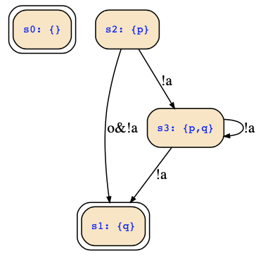
There are two inputs encoded by one boolean input variable a (which can be either true or false), and there are two outputs encoded by one boolean output variable o (which can be either true or false). Moreover, there are four possible states which are encoded by the four assignments to the two state variables p,q.
The transitions are encoded as the satisfying assignments of the transition relation R where next(p) and next(q) denote the values of the state variable in the target state of a transition, while p and q encode the source state. If I am writing pX for next(p) and qX for next(q), the transition relation will be represented by the following BDD:

This encodes the transitions with the corresponding inputs and outputs.
Of course, you may also use any other method to determine the satisfying assignments of the given formula. For example, we can also compute an equivalent DNF like the following one:
    p ∧ ¬a ∧ next(p) ∧ next(q) ∨
    p ∧ q ∧ ¬a ∧ ¬o ∧ ¬next(p) ∧ next(q) ∨
    p ∧ ¬a ∧ o ∧ ¬next(p) ∧ next(q)
Note that whenever a variable is not mentioned in one of the cubes above, it is a don't care. Expanding the DNF into full midterms, it will look as follows:
    p ∧ ¬q ∧ ¬a ∧ ¬o ∧  next(p) ∧ next(q) ∨
    p ∧ ¬q ∧ ¬a ∧  o ∧  next(p) ∧ next(q) ∨
    p ∧ ¬q ∧ ¬a ∧  o ∧ ¬next(p) ∧ next(q) ∨
    p ∧  q ∧ ¬a ∧  o ∧  next(p) ∧ next(q) ∨
    p ∧  q ∧ ¬a ∧  o ∧ ¬next(p) ∧ next(q) ∨
    p ∧  q ∧ ¬a ∧ ¬o ∧  next(p) ∧ next(q) ∨
    p ∧  q ∧ ¬a ∧ ¬o ∧ ¬next(p) ∧ next(q)
Hence, we find the following transition diagram (I hope that I read !p as the initial states correctly, otherwise, you need to adapt the initial states accordingly):