I hope that I answer your question correctly, and can give you some insights. There are two ways how you can describe the FSM, one is the implicit form using one boolean input variable a, one boolean output variable o, and two state variables p,q which then leads to the following initial condition and transition relation:
InitCond:
¬p∧¬q∨p∧¬q
TransRel:
¬p∧¬q ∧ a∧ o∧ next(p)∧¬next(q) ∨
¬p∧¬q ∧ ¬a∧ o∧¬next(p)∧ next(q) ∨
p∧¬q ∧ a∧¬o∧ next(p)∧ next(q) ∨
p∧ q ∧ ¬a∧¬o∧ next(p)∧ next(q)
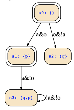
Inspecting the truth tables of both formulas gives us the state transition diagram below:
This has been computed with the tool https://es.cs.uni-kl.de/tools/teaching/SymbolicStateTrans.html , which can be used to convert a symbolic representation to an explicit one; simply type in the following:
- state variables: q;p
- input variables: a;o
- initial states: ¬p∧¬q∨p∧¬q
- transition relation: ¬p∧¬q ∧ a∧ o∧ next(p)∧¬next(q) ∨ ¬p∧¬q ∧ ¬a∧ o∧¬next(p)∧ next(q) ∨ p∧¬q ∧ a∧¬o∧ next(p)∧ next(q) ∨ p∧ q ∧ ¬a∧¬o∧ next(p)∧ next(q)
- state set: false
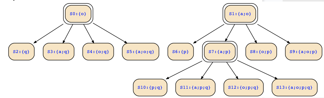
The tool can also show you the corresponding Kripke structure: Just modify the above input in that you remove all input variables and add those to the state variables. Then, the tool will give you the corresponding Kripke structure:
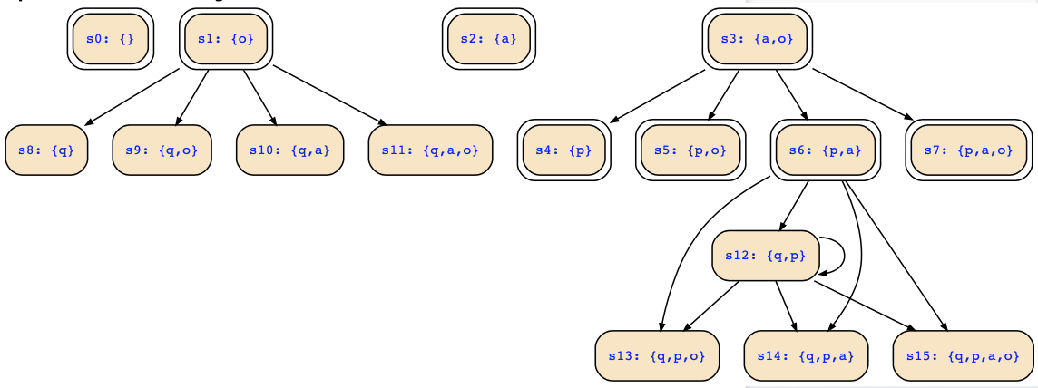
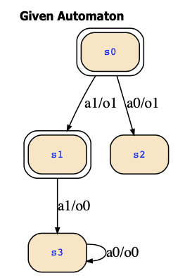
Now, let's consider the explicit representation and conversation to its Kripke structure. Here, the two inputs a and ¬a are encoded with the explicit inputs a1 and a0, respectively, and similarly, the two outputs o and ¬o are encoded with the explicit inputs o1 and o0, respectively. States 0,1,2,3 correspond with ¬p∧¬q, p∧¬q, ¬p∧q, p∧q, respectively. The FSM looks now as follows, and it obviously is the same FSM:
Using the tool https://es.cs.uni-kl.de/tools/teaching/Automata.html, you can convert the FSM to its corresponding Kripke structure:
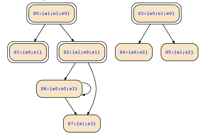
This time the Kripke structure looks different. Why is that so? Well, the names and labels are different due to our different encodings which does not matter. However, it is also seen that the structure obtained from the symbolic encoding has further states (and includes all the other ones). You can see the following correspondence between the two structures (note the use of captial letter S):
- S0:{a1;o1;s0} == s3:{a,o}
- S1:{a0;s1} == s4:{p}
- S2:{a1;o0;s1} == s6:{a;p}
- S3:{a0;o1;s0} == s1:{o}
- S4:{a0;s2} == s8:{q}
- S5:{a1;s2} == s10:{a;q}
- S6:{a0;o0;s3} == s12:{p;q}
- S7:{a1;s3} == s14:{a;p;q}
The additional states of the other structure are the deadend states that are states without transitions in the FSM, i.e.,
- s0:{}
- s2:{a}
- s5:{p,o}
- s7:{p,a,o}
- s9:{q,o}
- s11:{q,a,o}
- s13:{q,p,o}
- s15:{q,p,a,o}
The symbolic representation of the transition relation contains the transitions to these states, but there are no outgoing transitions. This is a consequence of the fact that the transition relation does neither mention next inputs nor does it mention next outputs so that these are not restricted for the target states of the transitions. These deadend states are not added in the explicit construction, since the explicit construction generates Kripke structure states for transitions of the FSM.
The FSM has however also states that cannot react to some inputs, and this leads to further deadend states:
- s4:{p}
- s8:{q}
- s10:{a;q}
- s14:{a;p;q}
These states of the Kripke structure describe states of the FSM that cannot react to the input given in the Kripke structure's state. Hence, there are also no outgoing transitions in the Kripke structure. If you remove those states, s1:{o} becomes another deadend state, and then only states s3,s6,s12 remain as the only states that have infinite outgoing paths. For reactive system models, only these three states of the structure are relevant, since all others have no infinite paths.
The exercise should state whether to add deadend states, and if so, note that there are actually two kinds of these:
- deadend states where wrong outputs were chosen for the specified input
- deadend states that correspond with missing transitions in the FSM
Note further that removing deadend states may make other states deadend states. In case the FSM has transitions for each input in each state, that will no happen.
Since an explicitly represented FSM was given in the exercise, I guess the exercise wants you to ignore the first kind of deadend states, but to retain the latter.
What is wrong with your solution? If I have drawn it correctly, it looks as follows:
Compare it with the structures above and see where you went wrong.